
Getting Started
This getting started guide walks you through the basics of Factory I/O, including: working with cameras, creating/editing scenes and controlling them with external technologies. At the end of this guide you will be able to create a virtual factory and use it together with your own PLC.
1. Navigating
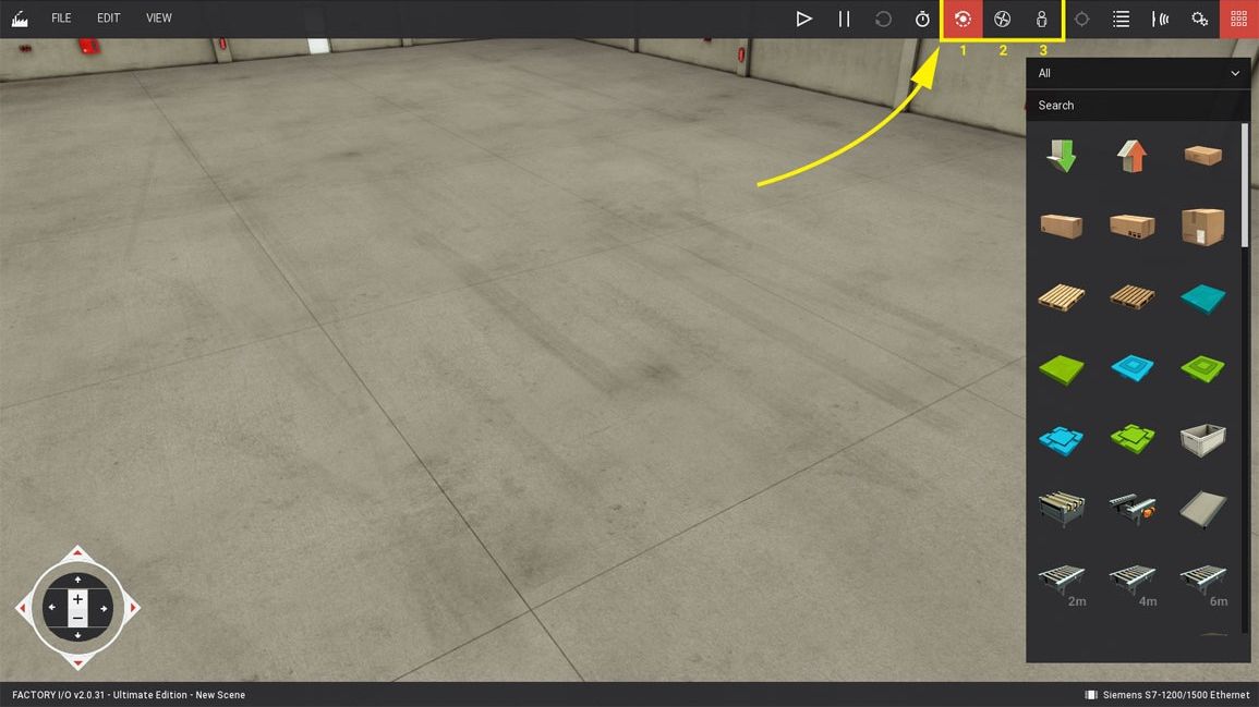
One of the most important skills to learn in Factory I/O is how to use cameras. Cameras are used to navigate in the 3D space and are the key to interacting with parts or building new scenes. You can use three types of cameras: Orbit (1), Fly (2) and First Person (3).
Get used to each type by testing the actions as described below. Keep in mind that each camera was designed for a specific functional purpose.
1. Orbit Camera
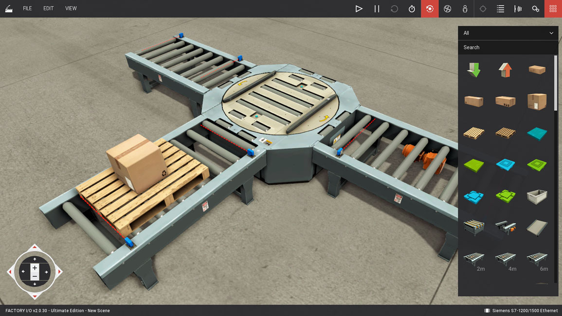
The Orbit camera is the default camera and should be used when building a scene. This is the only camera that allows you to move through parts without colliding with them.
It works by rotating around a point of interest (indicated by a white dot) which you define by Double Left-clicking on a part. Once the point of interest is defined, you rotate the camera around it by holding the Right Button and dragging the mouse. New parts dragged from the Palette are created at the height defined by this point, except for parts which are typically placed on the floor, such as conveyors, stations, etc.
| Control | Action |
|---|---|
| Double Left Button | Set the camera point of interest. The camera will rotate around this point, and new parts will be created at this height. |
| Right Button + Drag | Rotate around the point of interest. |
| Middle Button + Drag | Translate horizontally. |
| Mouse Wheel | Zoom in and out. |
| Backspace | Reset to the default position and rotation. |
| W or Up | Move forward. |
| S or Down | Move backward. |
| D or Right | Move right. |
| A or Left | Move left. |
2. Fly Camera
The Fly camera is used to move freely in the 3D space. This camera collides with scene parts but is not detected by sensors.
| Control | Action |
|---|---|
| Double Left Button | Point the camera to the mouse cursor. |
| Right Button + Drag | Rotate. |
| Mouse Wheel | Translate vertically. |
| Left Button + Right Button | Move forward. |
| W or Up | Move forward. |
| S or Down | Move backward. |
| A or Left | Move left. |
| D or Right | Move right. |
3. First Person Camera
The First Person camera represents a person of 1.8m (~5.9 feet) height. It should be used when simulating a person in a virtual factory. It collides with scene parts and, by default, is not detected by sensors.
You may set the First Person Camera to be detected by sensors using the console command camera.fp_detected = 1. Learn more about the Console.
| Control | Action |
|---|---|
| Double Left Button | Point the camera to the mouse cursor. |
| Right Button + Drag | Rotate the camera. |
| Left Button + Right Button | Move forward. |
| W or Up | Move forward. |
| S or Down | Move backward. |
| A or Left | Move left. |
| D or Right | Move right. |
| Space | Jump. |
Opening a Scen
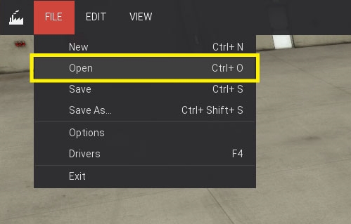
To open a scene choose Open (Ctrl+O) from the File Menu and select it from the list by Left-clicking.
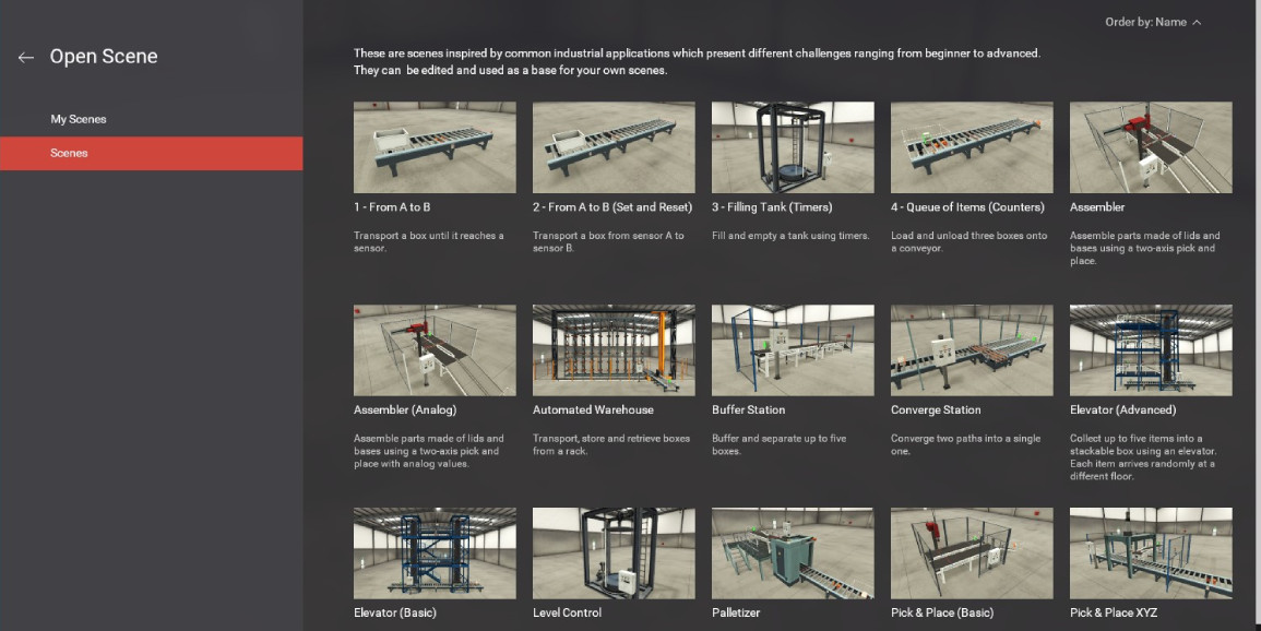
Factory I/O comes with 21 Scenes, which can be accessed under the Scenes tab. You may also use any of these scenes as a starting point for a new one by opening and saving it with a custom name.
Manually Controlling a Scene
Before controlling a scene with an external controller (a PLC, for instance) it’s recommended to test it manually. This way you can ensure that the scene layout works as expected. But first, you need to learn what Tags are and how they can be used to control parts.
Any part that is a sensor or actuator has at least one tag. Tags are made of a name and a value and can be of two different types: Sensors Tags and Actuators Tags. They can hold three different data types: Boolean for on/off values, Float for analog values (real numbers) and Integer for specific data.
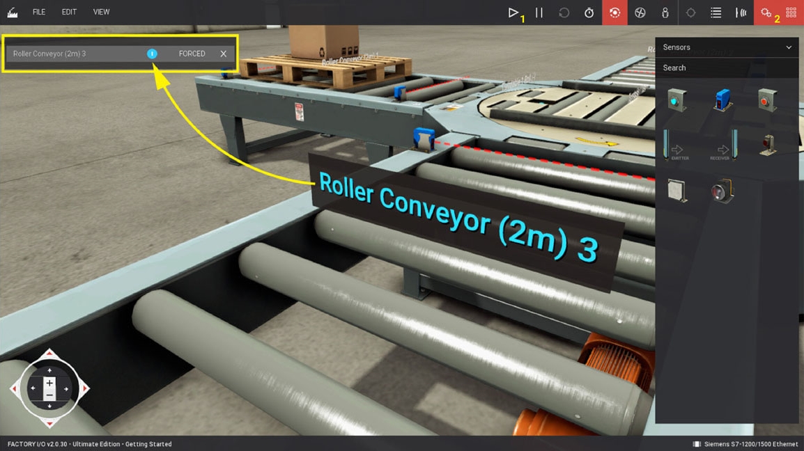
Tag values can be Forced at any moment, allowing you to play the role of the controller. To control your scene manually, you force the Actuators Tags, simulating a value coming from the controller.
Using the scene created on 3. Creating a Scene, try to transport the pallet to the left conveyor.
- Switch to Run mode by clicking the Play button (1).
- Show the actuators tags by clicking on the Actuators Tags button (2).
- Left-click on a tag to dock it. Once a tag is docked, you can force its value. You can Dock All Tags and Clear Docked Tags on the View Menu.
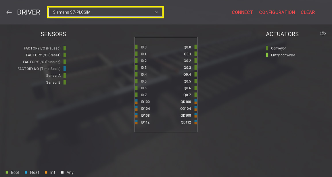
Siemens S7-PLCSIM
This driver provides connectivity with Siemens S7-PLCSIM. It can be used to control Factory I/O with S7-PLCSIM v5/13-16/Advanced through TIA Portal.
TIA Portal Template Projects
Note that you must use a TIA Portal template project when connecting with S7-PLCSIM v13-18. Without these templates, Factory I/O will not be able to communicate with this particular version of S7-PLCSIM.
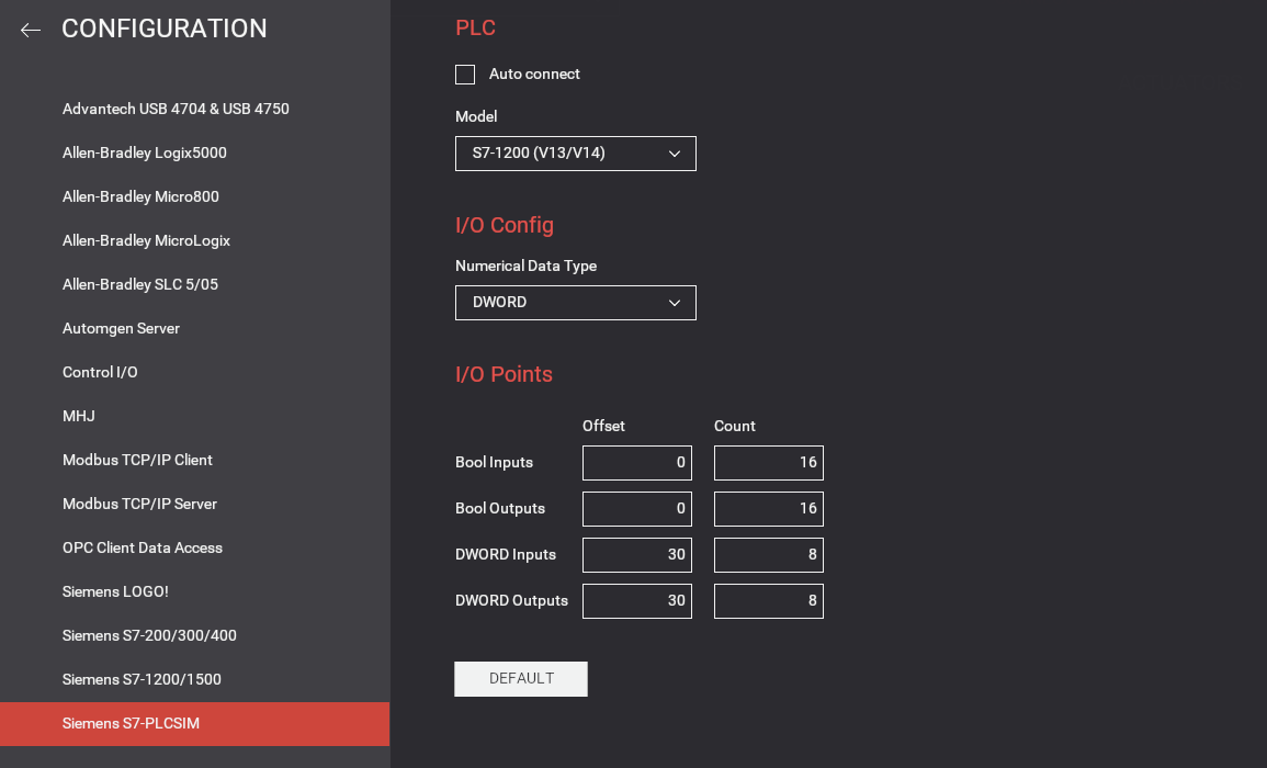
Configuration
| Configuration Setting | Description |
|---|---|
| Auto connect | Periodically tries to connect to the PLC until a successful connection is established. |
| Model | PLC model: S7-300, S7-1200, S7-1500 or S7-1500 (S7-PLCSIM Advanced).S7-PLCSIM Advanced must be configured with an instance name set to factoryio. You can change the instance name with the console command drivers.siemens_s7plcsim.instance_name = ‘newname’. |
| Numerical Data Type | Choose whether WORD or DWORD will be used for analog values. |
| Bool Inputs | Address offset and number of Bool inputs to use for digital sensors (max 256). Sensors’ values are written into I memories starting at address 0 (by default). |
| Bool Outputs | Address offset and number of Bool outputs to use for digital actuators (max 256). Actuators’ values are read from Q memories starting at address 0 (by default). |
| DWORD Inputs | Address offset and number of DWORD/WORD inputs to use for analog sensors (max 64). |
| DWORD Outputs | Address offset and number of DWORD/WORD outputs to use for analog actuators (max 64). |
| Default | Click to reset to the default options. |
About Analog Values
You should be aware of how floating and integer values are exchanged between Factory I/O and the PLC. The driver can be configured to read/write values using WORD or DWORD and the following list gives you detailed information on how data is encoded/decoded in both cases.
DWORD Inputs (Sensors)
- Floating sensor values are encoded as 32-bit floating point numbers (REAL).
- Integer sensor values are encoded as 32-bit integers.
DWORD Outputs (Actuators)
- Floating actuator values are expected as 32-bit floating point numbers (REAL).
- Integer actuator values are expected as 32-bit integers.
WORD Inputs (Sensors)
- Floating sensor values ranging from -10 V to 10 V are linearized between -27648 and 27648.
- Floating sensor values ranging from 0 V to 10 V are linearized between 0 and 27648.
- Integer sensor values are converted into signed 16-bit integers.
WORD Outputs (Actuators)
- Floating actuator values ranging from -10 V to 10 V are expected to be linearized between -27648 and 27648.
- Floating actuator values ranging from 0 V to 10 V are expected to be linearized between 0 and 27648.
- Integer actuator values are expected as signed 16-bit integers.
When using WORD, conversion between integer values and real number values can be done with the ‘SCALE_X’ and ‘NORM_X’ instructions.